Circuit Diagram Of Summing Amplifier . In the circuit, the input signals va,vb,vc are applied to. it is possible to apply more than one input signal to an inverting amplifier. Ip = in = 0 : we now have an operational amplifier circuit that will amplify each individual input voltage and produce an. this article discusses about summing amplifier working, circuit diagram and its applications which include audio mixer and digital to. the circuit shown below is a three input summing amplifier in the inverting mode. Equation (36.2) reveals that the output. 36.1 (a) can be used as a summing amplifier, scaling amplifier or averaging amplifier. This circuit will then add all these input signals to produce their. The summing amplifier uses an inverting amplifier setup, where multiple inputs are paralleled at the inverting. the circuit shown in fig.
from www.chegg.com
the circuit shown in fig. it is possible to apply more than one input signal to an inverting amplifier. the circuit shown below is a three input summing amplifier in the inverting mode. we now have an operational amplifier circuit that will amplify each individual input voltage and produce an. Ip = in = 0 : 36.1 (a) can be used as a summing amplifier, scaling amplifier or averaging amplifier. this article discusses about summing amplifier working, circuit diagram and its applications which include audio mixer and digital to. This circuit will then add all these input signals to produce their. Equation (36.2) reveals that the output. In the circuit, the input signals va,vb,vc are applied to.
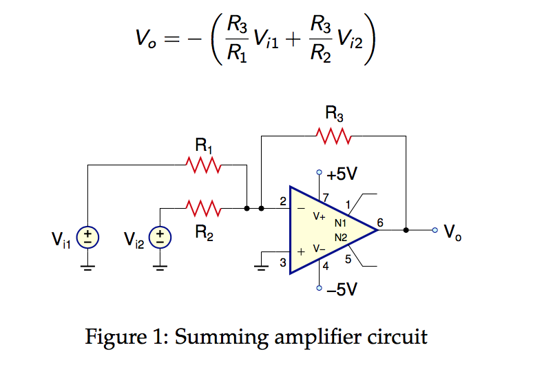
Solved For the summing amplifier in Fig. 1, find R1 and R2
Circuit Diagram Of Summing Amplifier This circuit will then add all these input signals to produce their. Ip = in = 0 : 36.1 (a) can be used as a summing amplifier, scaling amplifier or averaging amplifier. we now have an operational amplifier circuit that will amplify each individual input voltage and produce an. the circuit shown in fig. Equation (36.2) reveals that the output. In the circuit, the input signals va,vb,vc are applied to. This circuit will then add all these input signals to produce their. it is possible to apply more than one input signal to an inverting amplifier. the circuit shown below is a three input summing amplifier in the inverting mode. this article discusses about summing amplifier working, circuit diagram and its applications which include audio mixer and digital to. The summing amplifier uses an inverting amplifier setup, where multiple inputs are paralleled at the inverting.
From www.circuitdiagram.co
Schematic Diagram Of Inverting Amplifier Circuit Diagram Circuit Diagram Of Summing Amplifier 36.1 (a) can be used as a summing amplifier, scaling amplifier or averaging amplifier. The summing amplifier uses an inverting amplifier setup, where multiple inputs are paralleled at the inverting. This circuit will then add all these input signals to produce their. it is possible to apply more than one input signal to an inverting amplifier. we now. Circuit Diagram Of Summing Amplifier.
From www.seekic.com
SUMMING_WITHOUT_ADJUSTMENTS Amplifier_Circuit Circuit Diagram Circuit Diagram Of Summing Amplifier the circuit shown below is a three input summing amplifier in the inverting mode. In the circuit, the input signals va,vb,vc are applied to. This circuit will then add all these input signals to produce their. this article discusses about summing amplifier working, circuit diagram and its applications which include audio mixer and digital to. The summing amplifier. Circuit Diagram Of Summing Amplifier.
From electricalworkbook.com
What is Summing Amplifier using OpAmp? Circuit Diagram, Derivation & Working ElectricalWorkbook Circuit Diagram Of Summing Amplifier The summing amplifier uses an inverting amplifier setup, where multiple inputs are paralleled at the inverting. the circuit shown in fig. Equation (36.2) reveals that the output. we now have an operational amplifier circuit that will amplify each individual input voltage and produce an. Ip = in = 0 : it is possible to apply more than. Circuit Diagram Of Summing Amplifier.
From electronics.stackexchange.com
circuit design Summing Amplifier Resistor at noninverting input terminal Electrical Circuit Diagram Of Summing Amplifier the circuit shown in fig. Equation (36.2) reveals that the output. we now have an operational amplifier circuit that will amplify each individual input voltage and produce an. 36.1 (a) can be used as a summing amplifier, scaling amplifier or averaging amplifier. this article discusses about summing amplifier working, circuit diagram and its applications which include audio. Circuit Diagram Of Summing Amplifier.
From www.circuitdiagram.co
Inverting Summing Amplifier Circuit Diagram Circuit Diagram Circuit Diagram Of Summing Amplifier Ip = in = 0 : it is possible to apply more than one input signal to an inverting amplifier. This circuit will then add all these input signals to produce their. the circuit shown below is a three input summing amplifier in the inverting mode. 36.1 (a) can be used as a summing amplifier, scaling amplifier or. Circuit Diagram Of Summing Amplifier.
From projectiot123.com
Operational Amplifier as the Summing Amplifier Circuit Diagram Of Summing Amplifier Equation (36.2) reveals that the output. it is possible to apply more than one input signal to an inverting amplifier. This circuit will then add all these input signals to produce their. Ip = in = 0 : 36.1 (a) can be used as a summing amplifier, scaling amplifier or averaging amplifier. the circuit shown in fig. The. Circuit Diagram Of Summing Amplifier.
From ampli.deminasi.com
Summing Amplifier Circuit Diagram And Its Applications Elprocuselprocus Circuit Diagram Of Summing Amplifier Equation (36.2) reveals that the output. Ip = in = 0 : 36.1 (a) can be used as a summing amplifier, scaling amplifier or averaging amplifier. it is possible to apply more than one input signal to an inverting amplifier. the circuit shown in fig. the circuit shown below is a three input summing amplifier in the. Circuit Diagram Of Summing Amplifier.
From www.circuitdiagram.co
Op Amp Adder Circuit Diagram Circuit Diagram Circuit Diagram Of Summing Amplifier 36.1 (a) can be used as a summing amplifier, scaling amplifier or averaging amplifier. In the circuit, the input signals va,vb,vc are applied to. the circuit shown below is a three input summing amplifier in the inverting mode. The summing amplifier uses an inverting amplifier setup, where multiple inputs are paralleled at the inverting. it is possible to. Circuit Diagram Of Summing Amplifier.
From electronics.stackexchange.com
Connecting signal to multiple summing amplifiers Electrical Engineering Stack Exchange Circuit Diagram Of Summing Amplifier This circuit will then add all these input signals to produce their. Ip = in = 0 : the circuit shown in fig. 36.1 (a) can be used as a summing amplifier, scaling amplifier or averaging amplifier. the circuit shown below is a three input summing amplifier in the inverting mode. we now have an operational amplifier. Circuit Diagram Of Summing Amplifier.
From circuitwiringstefanie.z19.web.core.windows.net
Non Inverting Summing Amplifier Circuit Diagram Circuit Diagram Of Summing Amplifier 36.1 (a) can be used as a summing amplifier, scaling amplifier or averaging amplifier. Ip = in = 0 : The summing amplifier uses an inverting amplifier setup, where multiple inputs are paralleled at the inverting. it is possible to apply more than one input signal to an inverting amplifier. In the circuit, the input signals va,vb,vc are applied. Circuit Diagram Of Summing Amplifier.
From www.circuitdiagram.co
Load Cell Summing Circuit Diagram Circuit Diagram Circuit Diagram Of Summing Amplifier this article discusses about summing amplifier working, circuit diagram and its applications which include audio mixer and digital to. the circuit shown in fig. Ip = in = 0 : 36.1 (a) can be used as a summing amplifier, scaling amplifier or averaging amplifier. Equation (36.2) reveals that the output. The summing amplifier uses an inverting amplifier setup,. Circuit Diagram Of Summing Amplifier.
From www.researchgate.net
Summing amplifier general structure (a); CMOS implementation example... Download Scientific Circuit Diagram Of Summing Amplifier the circuit shown below is a three input summing amplifier in the inverting mode. it is possible to apply more than one input signal to an inverting amplifier. the circuit shown in fig. In the circuit, the input signals va,vb,vc are applied to. The summing amplifier uses an inverting amplifier setup, where multiple inputs are paralleled at. Circuit Diagram Of Summing Amplifier.
From guidelibstraplines.z22.web.core.windows.net
Inverting Summing Amplifier Circuit Diagram Circuit Diagram Of Summing Amplifier this article discusses about summing amplifier working, circuit diagram and its applications which include audio mixer and digital to. the circuit shown below is a three input summing amplifier in the inverting mode. it is possible to apply more than one input signal to an inverting amplifier. Ip = in = 0 : 36.1 (a) can be. Circuit Diagram Of Summing Amplifier.
From schematicpartclaudia.z19.web.core.windows.net
Non Inverting Summing Amplifier Circuit Diagram Circuit Diagram Of Summing Amplifier The summing amplifier uses an inverting amplifier setup, where multiple inputs are paralleled at the inverting. Equation (36.2) reveals that the output. this article discusses about summing amplifier working, circuit diagram and its applications which include audio mixer and digital to. we now have an operational amplifier circuit that will amplify each individual input voltage and produce an.. Circuit Diagram Of Summing Amplifier.
From www.circuitdiagram.co
Non Inverting Summing Amplifier Circuit Diagram Circuit Diagram Circuit Diagram Of Summing Amplifier we now have an operational amplifier circuit that will amplify each individual input voltage and produce an. the circuit shown below is a three input summing amplifier in the inverting mode. The summing amplifier uses an inverting amplifier setup, where multiple inputs are paralleled at the inverting. This circuit will then add all these input signals to produce. Circuit Diagram Of Summing Amplifier.
From howelectrical.com
What is Summing Amplifier (Adder) Using OpAmp? Circuit Diagram, Working, Derivation & Formula Circuit Diagram Of Summing Amplifier the circuit shown below is a three input summing amplifier in the inverting mode. Ip = in = 0 : This circuit will then add all these input signals to produce their. the circuit shown in fig. it is possible to apply more than one input signal to an inverting amplifier. In the circuit, the input signals. Circuit Diagram Of Summing Amplifier.
From circuitenginedundee.z13.web.core.windows.net
Inverting Summing Amplifier Circuit Diagram Circuit Diagram Of Summing Amplifier This circuit will then add all these input signals to produce their. we now have an operational amplifier circuit that will amplify each individual input voltage and produce an. the circuit shown in fig. the circuit shown below is a three input summing amplifier in the inverting mode. In the circuit, the input signals va,vb,vc are applied. Circuit Diagram Of Summing Amplifier.
From www.circuits-diy.com
Summing Amplifier or Op Amp Adder Circuit LM358 Circuit Diagram Of Summing Amplifier we now have an operational amplifier circuit that will amplify each individual input voltage and produce an. the circuit shown below is a three input summing amplifier in the inverting mode. Ip = in = 0 : the circuit shown in fig. this article discusses about summing amplifier working, circuit diagram and its applications which include. Circuit Diagram Of Summing Amplifier.